Z-Sense Installation
- Turn the printer on, and using the Maintenance menu, move the bed up to allow access to the underside of the Z plate.
- (optional) Turn the printer off, unplug the connectors from the bed, and remove the bed for better access to the Z-Sense mounting area.
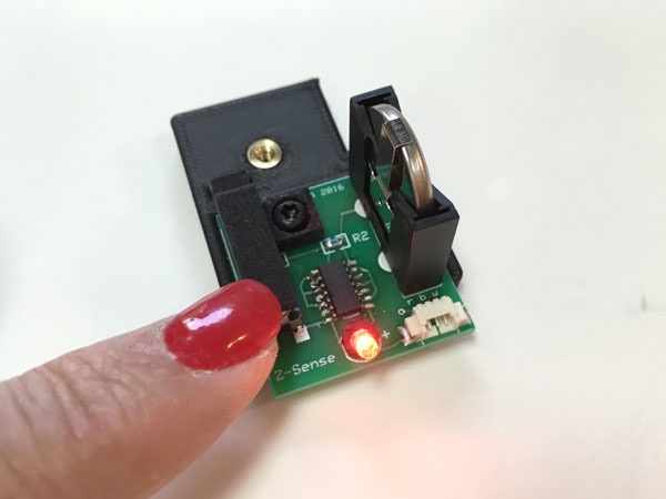
- Remove the insulating pull tab from the Z-Sense battery holder. Verify that pressing the sensor lever causes the LED to light (and that when the lever is released the LED turns off!).
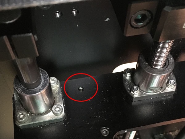
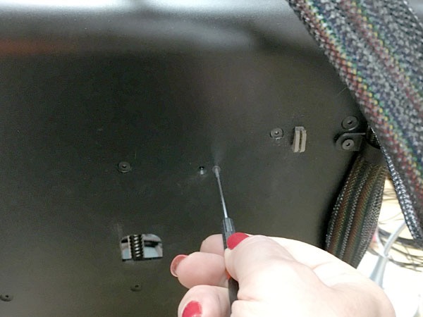
- Locate the PCB mounting hole on the Z-stage plate, next to the left-hand Z-rod.
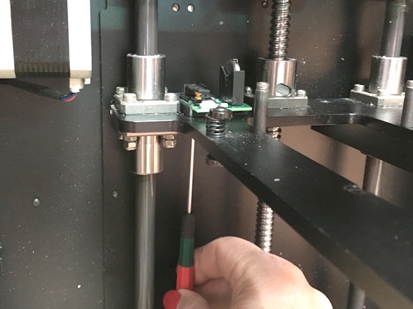
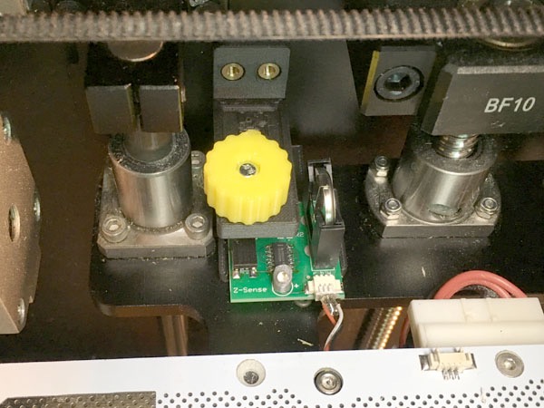
- Secure the PCB to the Z-stage plate with the included M3 x 12 socket-head screw and a 2.5mm hex driver. The screw is inserted from the under-side of the Z-plate and into the threaded insert in the PCB tray. The small lip at the rear of the PCB tray hangs over the rear edge of the Z-plate to prevent the PCB from rotating.
- Plug the small connector firmly into the Z-Sense connector.
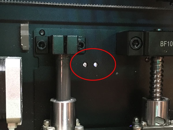
- Locate the adjuster bracket mounting holes in the rear wall of the printer.
- Mount the adjuster bracket to the rear wall of the printer using the included M3 x 10 flat-head screws and a 2mm hex driver. The fit of these screws through the holes in the printer frame may be tight due to chassis anodization thickness, but if you just keep turning the screws they will go. Tighten these screws firmly into the Z-Sense bracket so that there is no vertical play or movement of the adjuster bracket which could affect sensor accuracy.
- Re-install the bed if removed, and reconnect the large heater connector to the bed.
When removing the bed while Z-Sense is connected, please be careful not to pull the small connector wires!
Calibrating Z-Sense
While Z-Sense provides useful advantages over the M200’s electrical sensing scheme, it does not auto-compensates for nozzle and bed changes. Therefore, when using Z-Sense, the height setting must be reset any time the nozzle, bed, or hot end is changed. This is not difficult or time-consuming, but you do have to remember to do it!
Your bed should be level, or close to level, before calibrating Z-Sense. If you want to use the M200’s firmware auto-level feature, you’ll need to temporarily connect the small connector to the perfboard, then once your bed is level, plug it back into Z-Sense.
To calibrate Z-Sense, first you manually move the bed to a known distance from the nozzle, then you adjust the knob until the LED is right on its on/off threshold. Once this has been done you can then increase or decrease initial nozzle distance by turning the knob: one turn equals 0.5mm. Clockwise (viewed from the top) increases the initial distance, and counterclockwise reduces it.
If you calibrate Z-Sense with the nozzle touching the bed you will get the standard Zortrax nozzle distance and can then dial in any additional desired distance using the knob. Alternatively, you can calibrate directly to your final target distance, for example using the Z-Temp brass shim, in which case you’ll be set to a good distance for PLA and can offset up or down from there when and as needed.
Here in detail is one way to do the calibration:
- Turn the adjustment knob so that the screw protrudes from the bottom of the bracket by no more than 2mm or so, just to be sure that it won’t hit the switch when the bed is raised.
- With the printer off, move the print head carriage to the center of the build area. Remove any filament hanging from the nozzle.
- Turn the printer on, and using the Maintenance menu’s bed up/down controls, carefully move the bed until the nozzle is just barely touching the build plate - you can use a sheet of standard typing paper as a gauge - you should be able to slide the paper between the nozzle and the build plate with a little "drag". You may have to “poke” the M200 control knob in order to get very small up/down movements, or you can just grab the Z screw with your hand and turn it (forcing the stepper motor).
- Rotate the Z-Sense adjustment knob until the LED comes on, then rotate it counter-clockwise until it just turns off. Try to minimize vertical pressure on the knob when adjusting; the adjustment is sensitive, and the bracket, even though printed in carbon-fiber-reinforced PLA, has some inevitable flex. If you can tap lightly on the knob with your finger and make the LED flicker, it’s right on the trigger threshold.
- Now the printer is calibrated for the standard small initial layer height, good for ABS, polypropylene, or other materials that flow easily and/or require maximum adhesion help from the perfboard holes. Since the adjustment screw has a pitch of 0.5mm, each full rotation clockwise (viewed from above) will increase the initial layer height by 0.5mm. For most PLA we would turn the knob one full turn clockwise to add 0.5mm to the standard distance.
Again, please remember that the height setting must be reset any time the nozzle or bed is changed.
Note that if the printer is switched from Off to On while the Z-Sense LED is on, a “check small connector” error will be generated. To prevent this, be sure the Z-Sense LED is off (i.e. lower the bed) before switching the printer off.
Testing
If you don’t believe in Murphy, you can go ahead and start printing after calibrating your Z-Sense. The more cautious might want to do the following test first, just to make sure all the connections are working properly.
With the bed lowered to 100mm or so below the nozzle, launch a print. After the extruder has finished heating, the bed will start to move upward rapidly as usual for height calibration. When the bed is 50-75mm below the nozzle, press the Z-Sense trigger lever down with your finger. The LED should light and the bed should immediately stop moving rapidly upward - if it doesn’t, something is wrong - switch your printer off before the bed hits the nozzle! If everything’s working you can just let the height sensing cycle complete - it will take a while for the bed to complete its slow upward journey, but it will get there. Or you can switch the printer off and start over for a normal print cycle.
If the sensor did not work and you had to do an emergency abort, check that the small plug is fully seated in the Z-Sense’s socket.
Using the M200’s Firmware Auto-Leveling
The M200’s built-in firmware auto-leveling procedure does not work with Z-Sense. If you ever want to perform it, just unplug the small connector from Z-Sense and plug it into the bed temporarily while you perform auto-leveling.
Z-Sense Adjustment Range
Z-Sense’s adjustment screw has a fixed length and the adjustment bracket is mounted at a fixed height on the printer frame, so there is a limit to the range of platform thicknesses and hot end lengths it can accommodate. 5.3mm above the aluminum bed plate is about the maximum bed thickness that can be accommodated when using the ZT-HE hot end; this is equivalent to a v2 perfboard, a sheet of standard 3/32” window glass, and BuildTak™. To use a thicker build plate, you can reduce the total plate thickness by removing the perfboard and clipping the plate directly to the aluminum plate below.
When using a shorter hot end such as the Zortrax v1 or v2 (especially if using the thinner v1 perfboard), take care that the Z platform does not crash into the adjuster bracket and break it. An extra sheet of glass or other material can be used under the build surface to add height to the stackup and adjustment range in this case.